
substation civils · grid connections · HV foundations · earthing grids · duct banks · cable routes
What's in a Substation Civils Package? Foundations, Earthing, Duct Banks and Cable Routes
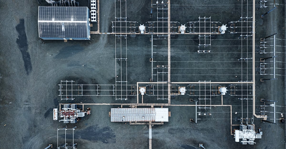
A substation civils package is not a collection of isolated groundworks. It is a tightly sequenced civil and structural programme in which the platform has to be right before the bases begin, the earthing has to be installed before slabs close it off, and buried cable routes have to be coordinated before structures restrict them.
At 110, 220 and 400 kV, the package can extend from bulk excavation and the engineered platform through control buildings, equipment bases, transformer plinths and blast walls, copper earthing grids, cable trenches, multi-way duct banks, joint bays and underground chambers. On a grid connection, the civil route can continue from the substation boundary to the network connection point.
The scope is physical, but its success depends on interfaces: with the plant that will sit on the foundations, with the earthing arrangement buried beneath concrete, with the cable and jointing teams that follow the civils, and with operations where work takes place inside or beside an energised compound. This article sets out those boundaries and explains what a complete handover needs to evidence.
The scope boundary at 110, 220 and 400 kV
The civil and structural scope across a high-voltage substation covers the built environment that supports, separates and connects the electrical plant. Maveric self-delivers that scope at 110, 220 and 400 kV, carrying it from bulk excavation through to a documented handover with its own crews and plant.
Within the compound, the package includes the engineered platform, control buildings and equipment plinths; reinforced transformer bases and blast walls; copper-tape and rod earthing grids; reinforced cable pits, joint bays and underground utility chambers; and cable trenches and multi-way duct banks for HV, MV and LV routes. Reinforcing-steel fabrication and fitting, formwork and concrete placing for sumps, plinths, foundations and blast walls sit within the same civil sequence.
Beyond the compound, grid-route civils connect the substation boundary to the network connection point. That route is formed through cable trenches, duct banks, joint bays and the chambers between them, built to the functional specification and connection requirements of the relevant transmission or distribution system operator.
- Bulk excavation and the engineered substation platform
- Control buildings and equipment plinths
- Transformer plinths, reinforced bases and blast walls
- Earthing grids in copper tape and rods
- Cable trenches and multi-way duct banks for HV, MV and LV
- Reinforced cable pits, joint bays and underground utility chambers
- Grid-route civils from the substation boundary to the network connection point
Why the package has to be managed as one sequence
Each element of the package fixes conditions for the next. The platform establishes the level and support for the structures above it. The foundations define where heavy plant will sit. Earthing conductors and rods have to be coordinated before concrete and slabs make the buried work inaccessible. Duct routes have to reach the right pits, chambers and equipment positions without being boxed out by later structures.
Treating those elements as disconnected appointments creates handoffs at the points where coordination matters most. Delivering them as one continuous civil package keeps the platform, buried services, reinforced structures and final record under one programme and one line of accountability.
The same sequencing discipline applies beyond the fence. A grid route has to be ready for cable pulling and jointing without rework, with joint bays positioned for the teams that follow and the chambers between them coordinated as part of the route rather than added afterwards.
Transformer plinths, foundations and blast walls
Transformer foundations are among the most demanding visible elements of the package. The reinforced bases and plinths carry heavy plant, while blast walls form part of the structural scope around it. Their delivery begins below the concrete, with the platform, formation and setting-out that establish the correct position and long-term stability for the structures above.
Maveric's civil scope includes reinforcing-steel fabrication and fitting, formwork and concrete placing for foundations, sumps, plinths and blast walls. Keeping those activities with the earthworks and buried-service teams allows the concrete sequence to be coordinated with the earthing and duct routes before access closes.
The interface is not only between trades. Foundations and equipment positions have to be built to the relevant project and system-operator requirements, while the surrounding ducting, pits and earthing remain coordinated with the plant that will be installed later.
Earthing-grid interfaces before concrete
The earthing grid is a buried part of the substation civils sequence, formed in copper tape and rods. Because slabs and reinforced bases close off the ground beneath them, the earthing arrangement has to be coordinated and installed before the concrete sequence removes access.
That makes earthing an interface rather than a late addition. The civil team has to hold the relationship between the grid, the foundations, equipment plinths, trenches and service corridors while each remains accessible. The earthing and civil arrangement are built to the functional specifications and connection requirements of the relevant transmission or distribution system operator, not to a generic groundworks standard.
The practical control is the sequence itself: platform first, buried arrangement coordinated before slabs, then foundations and structures. Inspection and test plans and the as-built record run package by package so the buried work is evidenced after it can no longer be seen.
HV duct banks, cable trenches and joint bays
The buried cable route links the equipment inside the compound and can continue out to the network connection point. Multi-way duct banks provide a structured underground pathway for cables, with conduits arranged in rows and columns and protected by concrete encasement or engineered backfill as the design requires.
Construction begins with the trench excavated to the designed line, level and width. A prepared bedding layer provides a stable surface, conduits are placed in their designed arrangement using spacers, and the run is checked before encasement. Conduits are typically tested, often by mandrel pull, before concrete is placed because a blockage found after encasement is much more difficult to correct. Compacted backfill and marker tape complete the buried route.
Within a substation and grid package, those runs have to be coordinated as a continuous route. Cable trenches, duct banks, reinforced cable pits, joint bays and underground chambers are sequenced so cabling and jointing can follow without reopening completed work.
Cable-route readiness before pulling and jointing
A completed trench is not necessarily a route the cable team can use. Before the civil package is handed across, check that the route shown on the latest design matches the installed path from the compound to the network connection point. Confirm the designed interfaces at equipment positions, chambers and joint bays, and check that access needed by the teams following the civils has not been blocked by later structures or hardstanding.
The construction record should close the same sequence it describes. Conduit-clearance checks are carried out before encasement where the specification requires them; the civil handover then identifies the installed line, depth and layout, the position of bays and chambers, and any differences from the intended route. The cable-pulling and jointing teams still have their own acceptance requirements. Readiness means the civil works and their evidence have been checked against the project design before that interface is signed off.
- Confirm the installed route and the chamber and joint-bay positions against the coordinated design.
- Confirm conduit clearance and the specified inspection hold points before inaccessible work is covered.
- Check that crossings, approaches to plant and access for following trades remain buildable.
- Carry the surveyed position, depth, layout and any approved changes into the as-built handover.
Joint bays and cable-route interfaces
A joint bay is the reinforced underground chamber where lengths of high-voltage cable are joined along the route. It is a structural element in its own right, positioned for the jointing teams that follow and built to keep water and ground movement out for the life of the circuit.
Its position is therefore both a civil and a cable-installation interface. The route into and out of the bay has to be set to line and level, the chamber has to be formed as part of the wider buried package, and the completed arrangement has to leave the jointing team with the access and route established in the design.
Delivering the bay separately from the duct banks and chambers around it breaks that continuity. Delivering the full route as one package keeps the structures and conduits tied to the same setting-out, programme and as-built record.
Working in or beside energised compounds
A large share of substation civils takes place inside or alongside an energised compound. Exclusion zones, permit-to-work regimes and the proximity of live high-voltage plant govern how tasks are planned, where plant can operate and when sections of work can proceed. The civil method has to be designed around those constraints from the outset and sequenced around outages and energisation.
Buried risk adds another interface. Ground-penetrating radar locates and marks existing services before ground is broken. Vacuum excavation then exposes a positively identified service without putting a digging edge into the ground around it. Trial holes and slot trenches can confirm depth and alignment before bulk excavation starts in congested ground.
The value lies in joining detection and exposure into one method. When the same self-delivered team carries both steps, the locate is less likely to be lost in a handoff between separate contractors. The approach is particularly relevant where services are live, the ground is congested or a strike could interrupt infrastructure on which an operational site depends.
Managing existing and new buried routes together
New duct banks cannot be planned in isolation from what is already in the ground. Existing HV cables, gas mains, water mains and telecoms ducts may sit close to the proposed route, particularly in operational or phased compounds. Records are a starting point, but on-site detection and positive exposure establish the conditions the excavation team is actually working around.
Once existing services have been identified, the new route can be set out and built around verified information rather than an assumption. The same digital thread then records both the services found and the infrastructure laid, so later phases do not have to repeat the uncertainty.
This link between safe digging and as-built capture matters because the same ground is often revisited. A locate that exists only as paint protects one excavation; a verified record supports future maintenance, expansion and construction planning.
What the handover documentation should evidence
A complete civil handover is more than a drawing of the intended arrangement. It should carry the record created as the package was built: inspection and test plans, material testing and as-built information captured package by package across the platform, buried services and reinforced structures.
For duct banks and cable routes, the as-built should reflect the true position, depth and layout of the installed infrastructure rather than only the original design intent. Every service identified and laid is captured through Maveric's in-house digital backbone and carried into the handover record.
That record gives the operator a defensible account of what is in the ground after trenches, slabs and hardstandings have closed it off. It also supports later excavation near the route by replacing assumptions with verified information.
- Inspection and test plans maintained package by package
- Material-testing records for the works delivered
- As-built records of services identified and infrastructure laid
- Verified position, depth and layout for duct banks and buried routes
- A coordinated record of the platform, buried services and reinforced civil structures
One civil package, several critical interfaces
The defining feature of a substation civils package is not any single structure. It is the need to keep the ground, concrete, earthing and cable-route interfaces coordinated through a sequence that becomes progressively harder to revisit.
At 110, 220 and 400 kV, that means controlling the platform before the foundations, the earthing before the slabs, the ducts before the structures close the route, and the joint bays before cabling and jointing begin. Where the compound is live, the same programme also has to work within exclusion zones, permits, outages and energisation constraints.
The package is complete when those physical works and their records agree: the foundations and blast walls are built, the earthing and duct routes are in place, existing services have been identified, and the handover shows what was actually delivered. Maveric carries out that work under one integrated management system aligned to ISO 45001 for safety, ISO 14001 for environment and ISO 9001 for quality.
Frequently asked questions
What is included in a substation civils package?
A substation civils package can include bulk excavation and the engineered platform, control buildings, equipment and transformer plinths, reinforced bases, blast walls, copper-tape and rod earthing grids, cable trenches, multi-way duct banks, joint bays, reinforced cable pits and underground utility chambers. Grid-route civils can continue from the substation boundary to the network connection point.
What voltage levels does substation civils work cover?
Maveric delivers substation and grid-connection civils at 110, 220 and 400 kV. The civil scope at those voltage levels includes the reinforced foundations, earthing grids and buried cable routes that support and connect the high-voltage plant.
Why must the earthing grid be coordinated before concrete is poured?
The earthing grid is installed in the ground in copper tape and rods. Slabs and reinforced bases close off access to that buried work, so the earthing arrangement has to be coordinated with foundations, plinths, trenches and service corridors before the concrete sequence proceeds.
What is the difference between a duct bank and a joint bay?
A duct bank is a protected underground pathway containing arranged conduits through which cables are pulled. A joint bay is the reinforced underground chamber where lengths of high-voltage cable are joined. They form connected parts of the same cable route and have to be set out and built as a coordinated civil package.
When is a grid-connection cable route ready for cable pulling?
The civil team must confirm that the built route, ducts, chambers and joint bays match the coordinated design, that the required conduit and inspection checks are complete, and that the as-built record identifies the installed position, depth and layout. Final acceptance for pulling and jointing follows the cable team's project-specific requirements.
Can substation civils be carried out beside energised equipment?
Yes. Work inside or alongside an energised compound is planned around exclusion zones, permit-to-work regimes, outages, energisation and the proximity of live high-voltage plant. Existing buried services are located and positively exposed before excavation where the ground is congested or live.